settembre 28, 2009

- Cisco Networking : Bridging and Switching Basics

Bridging and Switching Basics


This chapter introduces the technologies employed in devices loosely referred to as bridges and switches. Topics summarized here include general link layer device operations, local and remote bridging, ATM switching, and LAN switching. Chapters in Part V, "Bridging and Switching," address specific technologies in more detail.

What Are Bridges and Switches?

Bridges and switches are data communications devices that operate principally at Layer 2 of the OSI reference model. As such, they are widely referred to as data link layer devices.

Bridges became commercially available in the early 1980s. At the time of their introduction, bridges connected and enabled packet forwarding between homogeneous networks. More recently, bridging between different networks has also been defined and standardized.

Several kinds of bridging have proven important as internetworking devices. Transparent bridging is found primarily in Ethernet environments, while source-route bridging occurs primarily in Token Ring environments.Translational bridging provides translation between the formats and transit principles of different media types (usually Ethernet and Token Ring). Finally, source-route transparent bridging combines the algorithms of transparent bridging and source-route bridging to enable communication in mixed Ethernet/Token Ring environments.

Today, switching technology has emerged as the evolutionary heir to bridging-based internetworking solutions. Switching implementations now dominate applications in which bridging technologies were implemented in prior network designs. Superior throughput performance, higher port density, lower per-port cost, and greater flexibility have contributed to the emergence of switches as replacement technology for bridges and as complements to routing technology.

Link Layer Device Overview

Bridging and switching occur at the link layer, which controls data flow, handles transmission errors, provides physical (as opposed to logical) addressing, and manages access to the physical medium. Bridges provide these functions by using various link layer protocols that dictate specific flow control, error handling, addressing, and media-access algorithms. Examples of popular link layer protocols include Ethernet, Token Ring, and FDDI.

Bridges and switches are not complicated devices. They analyze incoming frames, make forwarding decisions based on information contained in the frames, and forward the frames toward the destination. In some cases, such as source-route bridging, the entire path to the destination is contained in each frame. In other cases, such as transparent bridging, frames are forwarded one hop at a time toward the destination.

Upper-layer protocol transparency is a primary advantage of both bridging and switching. Because both device types operate at the link layer, they are not required to examine upper-layer information. This means that they can rapidly forward traffic representing any network layer protocol. It is not uncommon for a bridge to move AppleTalk, DECnet, TCP/IP, XNS, and other traffic between two or more networks.

Bridges are capable of filtering frames based on any Layer 2 fields. For example, a bridge can be programmed to reject (not forward) all frames sourced from a particular network. Because link layer information often includes a reference to an upper-layer protocol, bridges usually can filter on this parameter. Furthermore, filters can be helpful in dealing with unnecessary broadcast and multicast packets.

By dividing large networks into self-contained units, bridges and switches provide several advantages. Because only a certain percentage of traffic is forwarded, a bridge or switch diminishes the traffic experienced by devices on all connected segments. The bridge or switch will act as a firewall for some potentially damaging network errors and will accommodate communication between a larger number of devices than would be supported on any single LAN connected to the bridge. Bridges and switches extend the effective length of a LAN, permitting the attachment of distant stations that was not previously permitted.

Although bridges and switches share most relevant attributes, several distinctions differentiate these technologies. Bridges are generally used to segment a LAN into a couple of smaller segments. Switches are generally used to segment a large LAN into many smaller segments. Bridges generally have only a few ports for LAN connectivity, whereas switches generally have many. Small switches such as the Cisco Catalyst 2924XL have 24 ports capable of creating 24 different network segments for a LAN. Larger switches such as the Cisco Catalyst 6500 can have hundreds of ports. Switches can also be used to connect LANs with different media—for example, a 10-Mbps Ethernet LAN and a 100-Mbps Ethernet LAN can be connected using a switch. Some switches support cut-through switching, which reduces latency and delays in the network, while bridges support only store-and-forward traffic switching. Finally, switches reduce collisions on network segments because they provide dedicated bandwidth to each network segment.

Types of Bridges

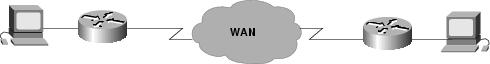
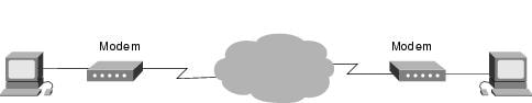
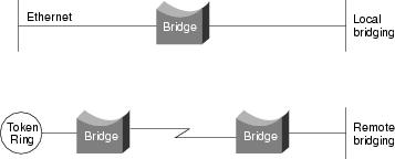
Bridges can be grouped into categories based on various product characteristics. Using one popular classification scheme, bridges are either local or remote. Local bridges provide a direct connection between multiple LAN segments in the same area. Remote bridges connect multiple LAN segments in different areas, usually over telecommunications lines. Figure 4-1 illustrates these two configurations.

Figure 4-1 Local and Remote Bridges Connect LAN Segments in Specific Areas

Remote bridging presents several unique internetworking challenges, one of which is the difference between LAN and WAN speeds. Although several fast WAN technologies now are establishing a presence in geographically dispersed internetworks, LAN speeds are often much faster than WAN speeds. Vast differences in LAN and WAN speeds can prevent users from running delay-sensitive LAN applications over the WAN.

Remote bridges cannot improve WAN speeds, but they can compensate for speed discrepancies through a sufficient buffering capability. If a LAN device capable of a 3-Mbps transmission rate wants to communicate with a device on a remote LAN, the local bridge must regulate the 3-Mbps data stream so that it does not overwhelm the 64-kbps serial link. This is done by storing the incoming data in onboard buffers and sending it over the serial link at a rate that the serial link can accommodate. This buffering can be achieved only for short bursts of data that do not overwhelm the bridge's buffering capability.

The Institute of Electrical and Electronic Engineers (IEEE) differentiates the OSI link layer into two separate sublayers: the Media Access Control (MAC) sublayer and the Logical Link Control (LLC) sublayer. The MAC sublayer permits and orchestrates media access, such as contention and token passing, while the LLC sublayer deals with framing, flow control, error control, and MAC sublayer addressing.

Some bridges are MAC-layer bridges, which bridge between homogeneous networks (for example, IEEE 802.3 and IEEE 802.3), while other bridges can translate between different link layer protocols (for example, IEEE 802.3 and IEEE 802.5). The basic mechanics of such a translation are shown in Figure 4-2.

Figure 4-2 A MAC-Layer Bridge Connects the IEEE 802.3 and IEEE 802.5 Networks

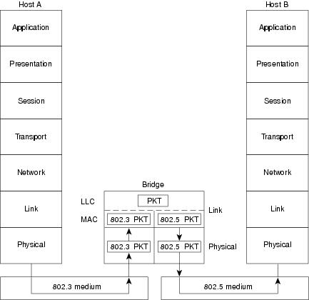
Figure 4-2 illustrates an IEEE 802.3 host (Host A) formulating a packet that contains application information and encapsulating the packet in an IEEE 802.3-compatible frame for transit over the IEEE 802.3 medium to the bridge. At the bridge, the frame is stripped of its IEEE 802.3 header at the MAC sublayer of the link layer and is subsequently passed up to the LLC sublayer for further processing. After this processing, the packet is passed back down to an IEEE 802.5 implementation, which encapsulates the packet in an IEEE 802.5 header for transmission on the IEEE 802.5 network to the IEEE 802.5 host (Host B).

A bridge's translation between networks of different types is never perfect because one network likely will support certain frame fields and protocol functions not supported by the other network.

Types of Switches

Switches are data link layer devices that, like bridges, enable multiple physical LAN segments to be interconnected into a single larger network. Similar to bridges, switches forward and flood traffic based on MAC addresses. Any network device will create some latency. Switches can use different forwarding techniques—two of these are store-and-forward switching and cut-through switching.

In store-and-forward switching, an entire frame must be received before it is forwarded. This means that the latency through the switch is relative to the frame size—the larger the frame size, the longer the delay through the switch. Cut-through switching allows the switch to begin forwarding the frame when enough of the frame is received to make a forwarding decision. This reduces the latency through the switch. Store-and-forward switching gives the switch the opportunity to evaluate the frame for errors before forwarding it. This capability to not forward frames containing errors is one of the advantages of switches over hubs. Cut-through switching does not offer this advantage, so the switch might forward frames containing errors. Many types of switches exist, including ATM switches, LAN switches, and various types of WAN switches.

ATM Switch

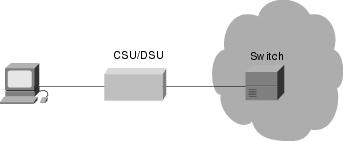
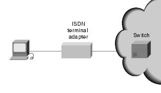
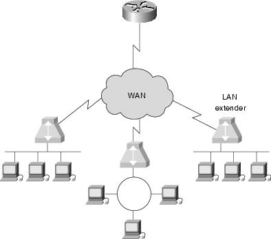
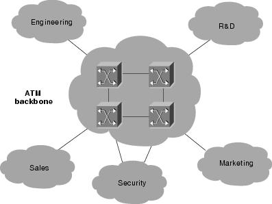
Asynchronous Transfer Mode (ATM) switches provide high-speed switching and scalable bandwidths in the workgroup, the enterprise network backbone, and the wide area. ATM switches support voice, video, and data applications, and are designed to switch fixed-size information units called cells, which are used in ATM communications. Figure 4-3 illustrates an enterprise network comprised of multiple LANs interconnected across an ATM backbone.

Figure 4-3 Multi-LAN Networks Can Use an ATM-Based Backbone When Switching Cells


LAN Switch

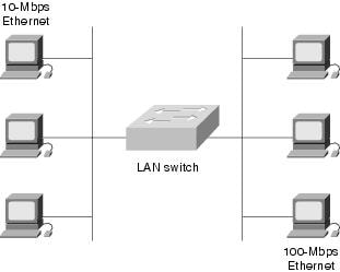
LAN switches are used to interconnect multiple LAN segments. LAN switching provides dedicated, collision-free communication between network devices, with support for multiple simultaneous conversations. LAN switches are designed to switch data frames at high speeds. Figure 4-4 illustrates a simple network in which a LAN switch interconnects a 10-Mbps and a 100-Mbps Ethernet LAN.

Figure 4-4 A LAN Switch Can Link 10-Mbps and 100-Mbps Ethernet Segments

Review Questions

Q—What layer of the OSI reference model to bridges and switches operate.

A—Bridges and switches are data communications devices that operate principally at Layer 2 of the OSI reference model. As such, they are widely referred to as data link-layer devices.

Q—What is controlled at the link layer?

A—Bridging and switching occur at the link layer, which controls data flow, handles transmission errors, provides physical (as opposed to logical) addressing, and manages access to the physical medium.

Q—Under one popular classification scheme what are bridges classified as?

A—Local or Remote: Local bridges provide a direct connection between multiple LAN segments in the same area. Remote bridges connect multiple LAN segments in different areas, usually over telecommunications lines.

Q—What is a switch?

A—Switches are data link-layer devices that, like bridges, enable multiple physical LAN segments to be interconnected into a single larger network.

- Cisco Networking : Introduction to WAN Technologies

Introduction to WAN Technologies


This chapter introduces the various protocols and technologies used in wide-area network (WAN) environments. Topics summarized here include point-to-point links, circuit switching, packet switching, virtual circuits, dialup services, and WAN devices. Chapters in Part III, "WAN Protocols," address specific technologies in more detail.

What Is a WAN?

A WAN is a data communications network that covers a relatively broad geographic area and that often uses transmission facilities provided by common carriers, such as telephone companies. WAN technologies generally function at the lower three layers of the OSI reference model: the physical layer, the data link layer, and the network layer. Figure 3-1 illustrates the relationship between the common WAN technologies and the OSI model.

Figure 3-1 WAN Technologies Operate at the Lowest Levels of the OSI Model

Point-to-Point Links

A point-to-point link provides a single, pre-established WAN communications path from the customer premises through a carrier network, such as a telephone company, to a remote network. Point-to-point lines are usually leased from a carrier and thus are often called leased lines. For a point-to-point line, the carrier allocates pairs of wire and facility hardware to your line only. These circuits are generally priced based on bandwidth required and distance between the two connected points. Point-to-point links are generally more expensive than shared services such as Frame Relay. Figure 3-2 illustrates a typical point-to-point link through a WAN.

Figure 3-2 A Typical Point-to-Point Link Operates Through a WAN to a Remote Network

Circuit Switching

Switched circuits allow data connections that can be initiated when needed and terminated when communication is complete. This works much like a normal telephone line works for voice communication. Integrated Services Digital Network (ISDN) is a good example of circuit switching. When a router has data for a remote site, the switched circuit is initiated with the circuit number of the remote network. In the case of ISDN circuits, the device actually places a call to the telephone number of the remote ISDN circuit. When the
two networks are connected and authenticated, they can transfer data. When the data transmission is complete, the call can be terminated. Figure 3-3 illustrates an example of this type of circuit.

Figure 3-3 A Circuit-Switched WAN Undergoes a Process Similar to That Used for a Telephone Call

Packet Switching

Packet switching is a WAN technology in which users share common carrier resources. Because this allows the carrier to make more efficient use of its infrastructure, the cost to the customer is generally much better than with point-to-point lines. In a packet switching setup, networks have connections into the carrier's network, and many customers share the carrier's network. The carrier can then create virtual circuits between customers' sites by which packets of data are delivered from one to the other through the network. The section of the carrier's network that is shared is often referred to as a cloud.

Some examples of packet-switching networks include Asynchronous Transfer Mode (ATM), Frame Relay, Switched Multimegabit Data Services (SMDS), and X.25. Figure
3-4 shows an example packet-switched circuit.

The virtual connections between customer sites are often referred to as a virtual circuit.

Figure 3-4 Packet Switching Transfers Packets Across a Carrier Network

WAN Virtual Circuits

A virtual circuit is a logical circuit created within a shared network between two network devices. Two types of virtual circuits exist: switched virtual circuits (SVCs) and permanent virtual circuits (PVCs).

SVCs are virtual circuits that are dynamically established on demand and terminated when transmission is complete. Communication over an SVC consists of three phases: circuit establishment, data transfer, and circuit termination. The establishment phase involves creating the virtual circuit between the source and destination devices. Data transfer involves transmitting data between the devices over the virtual circuit, and the circuit termination phase involves tearing down the virtual circuit between the source and destination devices. SVCs are used in situations in which data transmission between devices is sporadic, largely because SVCs increase bandwidth used due to the circuit establishment and termination phases, but they decrease the cost associated with constant virtual circuit availability.

PVC is a permanently established virtual circuit that consists of one mode: data transfer. PVCs are used in situations in which data transfer between devices is constant. PVCs decrease the bandwidth use associated with the establishment and termination of virtual circuits, but they increase costs due to constant virtual circuit availability. PVCs are generally configured by the service provider when an order is placed for service.

WAN Dialup Services

Dialup services offer cost-effective methods for connectivity across WANs. Two popular dialup implementations are dial-on-demand routing (DDR) and dial backup.

DDR is a technique whereby a router can dynamically initiate a call on a switched circuit when it needs to send data. In a DDR setup, the router is configured to initiate the call when certain criteria are met, such as a particular type of network traffic needing to be transmitted. When the connection is made, traffic passes over the line. The router configuration specifies an idle timer that tells the router to drop the connection when the circuit has remained idle for a certain period.

Dial backup is another way of configuring DDR. However, in dial backup, the switched circuit is used to provide backup service for another type of circuit, such as point-to-point or packet switching. The router is configured so that when a failure is detected on the primary circuit, the dial backup line is initiated. The dial backup line then supports the WAN connection until the primary circuit is restored. When this occurs, the dial backup connection is terminated.

WAN Devices

WANs use numerous types of devices that are specific to WAN environments. WAN switches, access servers, modems, CSU/DSUs, and ISDN terminal adapters are discussed in the following sections. Other devices found in WAN environments that are used in WAN implementations include routers, ATM switches, and multiplexers.

WAN Switch

A WAN switch is a multiport internetworking device used in carrier networks. These devices typically switch such traffic as Frame Relay, X.25, and SMDS, and operate at the data link layer of the OSI reference model. Figure 3-5 illustrates two routers at remote ends of a WAN that are connected by WAN switches.

Figure 3-5 Two Routers at Remote Ends of a WAN Can Be Connected by WAN Switches

Access Server

An access server acts as a concentration point for dial-in and dial-out connections. Figure 3-6 illustrates an access server concentrating dial-out connections into a WAN.

Figure 3-6 An Access Server Concentrates Dial-Out Connections into a WAN

Modem

A modem is a device that interprets digital and analog signals, enabling data to be transmitted over voice-grade telephone lines. At the source, digital signals are converted to a form suitable for transmission over analog communication facilities. At the destination, these analog signals are returned to their digital form. Figure 3-7 illustrates a simple modem-to-modem connection through a WAN.

Figure 3-7 A Modem Connection Through a WAN Handles Analog and Digital Signals

CSU/DSU

A channel service unit/digital service unit (CSU/DSU) is a digital-interface device used to connect a router to a digital circuit like a T1. The CSU/DSU also provides signal timing for communication between these devices. Figure 3-8 illustrates the placement of the CSU/DSU in a WAN implementation.

Figure 3-8 The CSU/DSU Stands Between the Switch and the Terminal

ISDN Terminal Adapter

An ISDN terminal adapter is a device used to connect ISDN Basic Rate Interface (BRI) connections to other interfaces, such as EIA/TIA-232 on a router. A terminal adapter is essentially an ISDN modem, although it is called a terminal adapter because it does not actually convert analog to digital signals. Figure 3-9 illustrates the placement of the terminal adapter in an ISDN environment.

Figure 3-9 The Terminal Adapter Connects the ISDN Terminal Adapter to Other Interfaces

Review Questions

Q—What are some types of WAN circuits?

A—Point-to-point, packet-switched, and circuit-switched.

Q—What is DDR, and how is it different from dial backup?

A—DDR is dial-on-demand routing. DDR dials up the remote site when traffic needs to be transmitted. Dial backup uses the same type of services, but for backup to a primary circuit. When the primary circuit fails, the dial backup line is initiated until the primary circuit is restored.

Q—What is a CSU/DSU used for?

A—A CSU/DSU interfaces a router with a digital line such as a T1.

Q—What is the difference between a modem and an ISDN terminal adapter?

A—A modem converts digital signals into analog for transmission over a telephone line. Because ISDN circuits are digital, the conversion from digital to analog is not required.

- Cisco Networking : Introduction to LAN Protocols

Introduction to LAN Protocols


This chapter introduces the various media-access methods, transmission methods, topologies, and devices used in a local-area network (LAN). Topics addressed focus on the methods and devices used in Ethernet/IEEE 802.3, Token Ring/IEEE 802.5, and Fiber Distributed Data Interface (FDDI). Subsequent chapters in Part II, "LAN Protocols," address specific protocols in more detail. Figure 2-1 illustrates the basic layout of these three implementations.

Figure 2-1 Three LAN Implementations Are Used Most Commonly

What Is a LAN?

A LAN is a high-speed data network that covers a relatively small geographic area. It typically connects workstations, personal computers, printers, servers, and other devices. LANs offer computer users many advantages, including shared access to devices and applications, file exchange between connected users, and communication between users via electronic mail and other applications.

LAN Protocols and the OSI Reference Model

LAN protocols function at the lowest two layers of the OSI reference model, as discussed in Chapter 1, "Internetworking Basics," between the physical layer and the data link layer. Figure 2-2 illustrates how several popular LAN protocols map to the OSI reference model.

Figure 2-2 Popular LAN Protocols Mapped to the OSI Reference Model

LAN Media-Access Methods

Media contention occurs when two or more network devices have data to send at the same time. Because multiple devices cannot talk on the network simultaneously, some type of method must be used to allow one device access to the network media at a time. This is done in two main ways: carrier sense multiple access collision detect (CSMA/CD) and token passing.

In networks using CSMA/CD technology such as Ethernet, network devices contend for the network media. When a device has data to send, it first listens to see if any other device is currently using the network. If not, it starts sending its data. After finishing its transmission, it listens again to see if a collision occurred. A collision occurs when two devices send data simultaneously. When a collision happens, each device waits a random length of time before resending its data. In most cases, a collision will not occur again between the two devices. Because of this type of network contention, the busier a network becomes, the more collisions occur. This is why performance of Ethernet degrades rapidly as the number of devices on a single network increases.

In token-passing networks such as Token Ring and FDDI, a special network frame called a token is passed around the network from device to device. When a device has data to send, it must wait until it has the token and then sends its data. When the data transmission is complete, the token is released so that other devices may use the network media. The main advantage of token-passing networks is that they are deterministic. In other words, it is easy to calculate the maximum time that will pass before a device has the opportunity to send data. This explains the popularity of token-passing networks in some real-time environments such as factories, where machinery must be capable of communicating at a determinable interval.

For CSMA/CD networks, switches segment the network into multiple collision domains. This reduces the number of devices per network segment that must contend for the media. By creating smaller collision domains, the performance of a network can be increased significantly without requiring addressing changes.

Normally CSMA/CD networks are half-duplex, meaning that while a device sends information, it cannot receive at the time. While that device is talking, it is incapable of also listening for other traffic. This is much like a walkie-talkie. When one person wants to talk, he presses the transmit button and begins speaking. While he is talking, no one else on the same frequency can talk. When the sending person is finished, he releases the transmit button and the frequency is available to others.

When switches are introduced, full-duplex operation is possible. Full-duplex works much like a telephone—you can listen as well as talk at the same time. When a network device is attached directly to the port of a network switch, the two devices may be capable of operating in full-duplex mode. In full-duplex mode, performance can be increased, but
not quite as much as some like to claim. A 100-Mbps Ethernet segment is capable of transmitting 200 Mbps of data, but only 100 Mbps can travel in one direction at a time. Because most data connections are asymmetric (with more data traveling in one direction than the other), the gain is not as great as many claim. However, full-duplex operation does increase the throughput of most applications because the network media is no longer shared. Two devices on a full-duplex connection can send data as soon as it is ready.

Token-passing networks such as Token Ring can also benefit from network switches. In large networks, the delay between turns to transmit may be significant because the token is passed around the network.

LAN Transmission Methods

LAN data transmissions fall into three classifications: unicast, multicast, and broadcast.
In each type of transmission, a single packet is sent to one or more nodes.

In a unicast transmission, a single packet is sent from the source to a destination on a network. First, the source node addresses the packet by using the address of the destination node. The package is then sent onto the network, and finally, the network passes the packet to its destination.

A multicast transmission consists of a single data packet that is copied and sent to a specific subset of nodes on the network. First, the source node addresses the packet by using a multicast address. The packet is then sent into the network, which makes copies of the packet and sends a copy to each node that is part of the multicast address.

A broadcast transmission consists of a single data packet that is copied and sent to all nodes on the network. In these types of transmissions, the source node addresses the packet by using the broadcast address. The packet is then sent on to the network, which makes copies of the packet and sends a copy to every node on the network.

LAN Topologies

LAN topologies define the manner in which network devices are organized. Four common LAN topologies exist: bus, ring, star, and tree. These topologies are logical architectures, but the actual devices need not be physically organized in these configurations. Logical bus and ring topologies, for example, are commonly organized physically as a star. A bus topology is a linear LAN architecture in which transmissions from network stations propagate the length of the medium and are received by all other stations. Of the three
most widely used LAN implementations, Ethernet/IEEE 802.3 networks—including 100BaseT—implement a bus topology, which is illustrated in Figure 2-3.

Figure 2-3 Some Networks Implement a Local Bus Topology

A ring topology is a LAN architecture that consists of a series of devices connected to one another by unidirectional transmission links to form a single closed loop. Both Token Ring/IEEE 802.5 and FDDI networks implement a ring topology. Figure 2-4 depicts a logical ring topology.

Figure 2-4 Some Networks Implement a Logical Ring Topology

A star topology is a LAN architecture in which the endpoints on a network are connected to a common central hub, or switch, by dedicated links. Logical bus and ring topologies are often implemented physically in a star topology, which is illustrated in Figure 2-5.

A tree topology is a LAN architecture that is identical to the bus topology, except that branches with multiple nodes are possible in this case. Figure 2-5 illustrates a logical tree topology.

Figure 2-5 A Logical Tree Topology Can Contain Multiple Nodes

LAN Devices

Devices commonly used in LANs include repeaters, hubs, LAN extenders, bridges, LAN switches, and routers.


Note Repeaters, hubs, and LAN extenders are discussed briefly in this section. The function and operation of bridges, switches, and routers are discussed generally in Chapter 4, "Bridging and Switching Basics," and Chapter 5, "Routing Basics."


A repeater is a physical layer device used to interconnect the media segments of an extended network. A repeater essentially enables a series of cable segments to be treated as a single cable. Repeaters receive signals from one network segment and amplify, retime, and retransmit those signals to another network segment. These actions prevent signal deterioration caused by long cable lengths and large numbers of connected devices. Repeaters are incapable of performing complex filtering and other traffic processing. In addition, all electrical signals, including electrical disturbances and other errors, are repeated and amplified. The total number of repeaters and network segments that can be connected is limited due to timing and other issues. Figure 2-6 illustrates a repeater connecting two network segments.

Figure 2-6 A Repeater Connects Two Network Segments

A hub is a physical layer device that connects multiple user stations, each via a dedicated cable. Electrical interconnections are established inside the hub. Hubs are used to create a physical star network while maintaining the logical bus or ring configuration of the LAN. In some respects, a hub functions as a multiport repeater.

A LAN extender is a remote-access multilayer switch that connects to a host router. LAN extenders forward traffic from all the standard network layer protocols (such as IP, IPX, and AppleTalk) and filter traffic based on the MAC address or network layer protocol type. LAN extenders scale well because the host router filters out unwanted broadcasts and multicasts. However, LAN extenders are not capable of segmenting traffic or creating security firewalls. Figure 2-7 illustrates multiple LAN extenders connected to the host router through a WAN.

Figure 2-7 Multiple LAN Extenders Can Connect to the Host Router Through a WAN

Review Questions

Q—Describe the type of media access used by Ethernet.

A—Ethernet uses carrier sense multiple access collision detect (CSMA/CD). Each network station listens before and after transmitting data. If a collision is detected, both stations wait a random time before trying to resend.

Q—Describe the type of media access used by Token Ring.

A—Token Ring passes a special type of packet called a token around the network. If a network device has data to send, it must wait until it has the token to send it. After the data has been sent, the token is released back on the network.

Q—Describe unicast, multicast, and broadcast transmissions.

A—A unicast is a transmission from one source to one destination. A multicast is a transmission from one source to many stations that register to receive the traffic. A broadcast is a transmission from one source to every station on the local network segment.