Contents
Introduction
Prerequisites
Requirements
Components Used
Overview
Goals
Access Control List Overview
NAT Overview
Configure
Get Started
Topology
Step 1 - Configure NAT to Allow Hosts to Go Out to Internet
Step 2 - Configure NAT to Access Webserver from Internet
Step 3 - Configure ACLs
Step 4 - Test Configuration with Packet Tracer Feature
Verify
Troubleshoot
Conclusion
Introduction
This document provides a simple and straight forward example of how to configure NAT and Access Control Lists (ACLs) on an ASA Firewall in order to allow outbound as well as inbound connectivity. This document was written using an ASA 5510 Firewall running ASA code version 9.1(1) but this can easily apply to any other ASA Firewall platform. If using a platform such as an ASA 5505, which uses VLANs instead of physical interface, you need to change the interface types as appropriate.
Prerequisites
Requirements
There are no specific requirements for this document.
Components Used
The information in this document is based on ASA 5510 Firewall running ASA code version 9.1(1).
The information in this document was created from the devices in a specific lab environment. All of the devices used in this document started with a cleared (default) configuration. If your network is live, make sure that you understand the potential impact of any command.
Overview
Goals
In this example configuration, you can look at what NAT and Access Control List configuration will be needed to configure in order to allow inbound access to a webserver in the DMZ of an ASA Firewall, and allow outbound connectivity from internal and DMZ hosts. This can be summarized as two goals:
- Allow hosts on the inside and DMZ outbound connectivity to the Internet.
- Allow hosts on the Internet to access a webserver on the DMZ with an IP address of 192.168.1.100.
Before getting to what steps must be done to accomplish these two goals, briefly go over the way Access Lists and NAT work on the newer versions of ASA code (version 8.3 and later).
Access Control List Overview
Access Control Lists (Access-lists or ACLs for short) are the method by which the ASA firewall determines if traffic is permitted or denied. By default, traffic passing from a lower to higher security level is denied. This can be overridden by an ACL applied to that lower security interface. Also the ASA, by default, will allow traffic from higherto lower security interfaces. This behavior can also be overridden with an ACL.
In earlier versions of ASA code (8.2 and earlier), the ASA compared an incoming connection or packet against the ACL on an interface without un-translating the packet first. In other words, the ACL had to permit the packet as if you were to capture that packet on the interface. In 8.3 and later code, the ASA un-translates that packet before checking the interface ACLs. This means that for 8.3 and later code, and this document, traffic to the host's real IP is permitted and not the host's translated IP.
NAT Overview
NAT on the ASA in version 8.3 and later is broken into two types knows as Auto NAT (Object NAT) and Manual NAT (Twice NAT). The first of the two, Object NAT, is configured within the definition of a network object. An example of this is provided later in this document. One primary advantage of this NAT method is that the ASA automatically orders the rules for processing as to avoid conflicts. This is the easiest form of NAT, but with that ease comes a limitation in configuration granularity. For example, you cannot make translation decision based on the destination in the packet as you could with the second type of nat, Manual Nat. Manual NAT is more robust in its granularity, but it requires that the lines be configured in the correct order in order to achieve the correct behavior. This complicates this NAT type and as a result, it will not be used in this configuration example.
Get Started
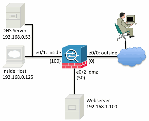
The basic ASA configuration setup is three interfaces connected to three network segments. The ISP network segment is connected to the Ethernet0/0 interface and labelled outside with a security level of 0. The internal network has been connected to Ethernet0/1 and labelled as inside with a security level of 100. The DMZ segment, where the webserver resides is connected to Ethernet0/2 and labelled as dmz with a security level of 50.
The interface configuration and IP addresses for the example is seen here:
interface Ethernet0/0
 nameif outside
 security-level 0
 ip address 198.51.100.100 255.255.255.0
!
interface Ethernet0/1
 nameif inside
 security-level 100
 ip address 192.168.0.1 255.255.255.0
!
interface Ethernet0/2
 nameif dmz
 security-level 50
 ip address 192.168.1.1 255.255.255.0
!
route outside 0.0.0.0 0.0.0.0 198.51.100.1
Here you can see that the ASA's inside interface is set with the IP address of 192.168.0.1, and it is the default gateway for the internal hosts. The ASA's outside interface is configured with an IP address obtained from the ISP. There is a default route in place, setting the next-hop to be the ISP gateway. If you use DHCP this is provided automatically. The dmz interface is configured with the IP address of 192.168.1.1, and it is the default gateway for hosts on our DMZ network segment.
Topology
Here is a visual look at how this is cabled and configured:
Step 1 - Configure NAT to Allow Hosts to Go Out to Internet
For this example Object NAT, also known as AutoNAT, is used. The first thing to configure is the NAT rules that allow the hosts on the inside and dmz segments to connect to the Internet. Beacuse these hosts are using private IP addresses, you need to translate them to something that is routable on the Internet. In this case translate the address so that they look like the ASA's outside interface IP address. If your external IP changes frequently (perhaps due to DHCP) this is the most straight forward way to set this up.
In order to configure this NAT, you need to create a network object that represents the inside subnet as well as one that represents the dmz subnet. In each of these objects, configure a dynamic nat rule that will PAT these clients as the pass from their respective interfaces to the outside interface.
This configuration looks similar to this:
object network inside-subnet
 subnet 192.168.0.0 255.255.255.0
 nat (inside,outside) dynamic interface
!
object network dmz-subnet
 subnet 192.168.1.0 255.255.255.0
 nat (dmz,outside) dynamic interface
If you look at the running configuration at this point (with the output of show run), you will see that the object definition is split into two parts of the output. The first part only indicates what is in the object (host/subnet, IP address, etc), while the second section shows that NAT rule tied to that object. If you take the first entry in the output above:
When hosts matching the 192.168.0.0/24 subnet traverse from the inside interface to the outside interface, we want to dynamically translate them to the outside interface
Step 2 - Configure NAT to Access Webserver from Internet
Now that the hosts on the inside and dmz interfaces can get out to the Internet, you need to modify the configuration so that users on the Internet can access our webserver on TCP port 80. In this example, the set up is so that people on the Internet can connect to another IP address the ISP provided, an additional IP address we own. For this example, use 198.51.100.101. With this configuration, users on the Internet will be able to reach the dmzwebserver by accessing 198.51.100.101 on TCP port 80. Use Object NAT for this task, and the ASA will be translating TCP port 80 on the webserver (192.168.1.100) to look like 198.51.100.101 on TCP port 80 on theoutside. Similarly to what was done above, define an object and define translation rules for that object. Also, define a second object to represent the IP you are translating this host to.
This configuration looks similar to this:
object network webserver-external-ip
 host 198.51.100.101
!
object network webserver
 host 192.168.1.100
 nat (dmz,outside) static webserver-external-ip service tcp www www
Just to summarize what that NAT rule means in this example:
When a host matching the ip address 192.168.1.100 on the dmz segments establishes a connection sourced fromTCP port 80 (www) and that connection goes out the outside interface, we want to translate that to be TCP port 80 (www) on the outside interface and translate that IP address to be 198.51.100.101
That seems a little odd... "sourced from TCP port 80 (www)", but web traffic is destined to port 80. It is important to understand that these NAT rules are bi-directional in nature. As a result you can re-phrase this sentence by flipping the wording around. The result makes a lot more sense:
When hosts on the outside establish a connection to 198.51.100.101 on destination TCP port 80 (www), we will translate the destination IP address to be 192.168.1.100 and the destination port will be TCP port 80 (www) and send it out the dmz
This makes more sense when phrased this way. Next, you need to set up the ACLs.
Step 3 - Configure ACLs
NAT is configured and the end of this configuration is near. Remember, ACLs on the ASA allow you to override the default security behavior which is as follows:
- Traffic going from a lower security interface is denied when going to a higher security interface
- Traffic going from a higher security interface is allowed when going to a lower security interface
So without adding any ACLs at all to the configuration, the following traffic in this example works:
- Hosts on the inside (security level 100) can connect to hosts on the dmz (security level 50)
- Hosts on the inside (security level 100) can connect to hosts on the outside (security level 0)
- Hosts on the dmz (security level 50) can connect to hosts on the outside (security level 0)
However, the following traffic is denied:
- Hosts on the outside (security level 0) cannot connect to hosts on the inside (security level 100)
- Hosts on the outside (security level 0) cannot connect to hosts on the dmz (security level 50)
- Hosts on the dmz (security level 50) cannot connect to hosts on the inside (security level 100)
Because traffic from the outside to the dmz network is denied by the ASA with its current configuration, users on the Internet cannot reach the webserver despite the NAT configuration in step 2. You need to explicitly permit this traffic. In 8.3 and later code you must use the Real IP of the host in the ACL and not the translated IP. This means the configuration needs to permit traffic destined to 192.168.1.100 and NOT traffic destined to 198.51.100.101 on port 80. For simplicity sake, the objects defined in step 2 will be used for this ACL as well. Once the ACL is created, you need to apply it inbound on the outside interface.
Here is what those configuration commands look like:
access-list outside_acl extended permit tcp any object webserver eq www
!
access-group outside_acl in interface outside
The access-list line states:
Permit traffic from any(where) to the host represented by the object webserver (192.168.1.100) on port 80
It is important the configuration uses the any keyword here. Because the source IP address of clients is not known reaching your website specify any meaning 'Any IP address'.
What about traffic from the dmz segment destined to hosts on the inside network segment? For example, a server on the inside network that the hosts on the dmz need to connect to? How can the ASA allow only that specific traffic destined to the inside server and block everything else destined to the inside segment from the dmz?
In this example it is assumed that there is a DNS server on the inside network at IP address 192.168.0.53 that the hosts on the dmz need to access for DNS resolution. You create the ACL needed and apply it to the dmz interface so the ASA can override that default security behavior, mentioned earlier, for traffic entering that interface.
Here is what those configuration commands look like:
object network dns-server
 host 192.168.0.53
!
access-list dmz_acl extended permit udp any object dns-server eq domain
access-list dmz_acl extended deny ip any object inside-subnet
access-list dmz_acl extended permit ip any any
!
access-group dmz_acl in interface dmz
The ACL is more complex that simply permitting that traffic to the DNS server on UDP port 53. If all we did is that first 'permit' line, then all traffic would be blocked from the dmz to hosts on the internet. Access-list have an implicit 'deny ip any any' at the end of the ACL. As a result, your dmz hosts would not be able to go out to the internet. Even though traffic from the dmz to the outside is permitted by default, by applying an ACL to the dmz interface, those default security behaviors for the dmz interface are no longer in effect and we must explicitly permit the traffic in the interface ACL.
Step 4 - Test Configuration with Packet Tracer Feature
Now that the configuration is completed, you need to test it to make sure it works. The easiest method is to use actual hosts (if this is your network). However, in the interest of testing this from the command line and further exploring some of the ASA's tools, use the packet tracer to test and potentially debug any problems encountered.
Packet tracer works by simulating a packet based on a series of parameters and injecting that packet to the interface data-path, similar to a real life packet would if it was picked up off the wire. This packet is followed through the myriad of the checks and processes that are done on as it passes through the firewall and packet tracer notes the outcome. Simulate the internal host going out to a host on the Internet. The command below instructs the firewall to:
Simulate a TCP packet coming in the inside interface from ip address 192.168.0.125 on source port 12345destined to an ip address of 203.0.113.1 on port 80
ciscoasa# packet-tracer input inside tcp 192.168.0.125 12345 203.0.113.1 80

Phase: 1
Type: ACCESS-LIST
Subtype:
Result: ALLOW
Config:
Implicit Rule
Additional Information:
MAC Access list

Phase: 2
Type: ROUTE-LOOKUP
Subtype: input
Result: ALLOW
Config:
Additional Information:
in   0.0.0.0         0.0.0.0         outside

Phase: 3
Type: NAT
Subtype:
Result: ALLOW
Config:
object network inside-subnet
 nat (inside,outside) dynamic interface
Additional Information:
Dynamic translate 192.168.0.125/12345 to 198.51.100.100/12345

Phase: 4
Type: NAT
Subtype: per-session
Result: ALLOW
Config:
Additional Information:

Phase: 5
Type: IP-OPTIONS
Subtype:
Result: ALLOW
Config:
Additional Information:

Phase: 6
Type: NAT
Subtype: per-session
Result: ALLOW
Config:
Additional Information:

Phase: 7
Type: IP-OPTIONS
Subtype:
Result: ALLOW
Config:
Additional Information:

Phase: 8
Type: FLOW-CREATION
Subtype:
Result: ALLOW
Config:
Additional Information:
New flow created with id 1, packet dispatched to next module

Result:
input-interface: inside
input-status: up
input-line-status: up
output-interface: outside
output-status: up
output-line-status: up
Action: allow
The end result is that the traffic is allowed meaning that it passed all the NAT and ACL checks in the configuration and was sent out the egress interface, outside. Note that the packet was translated in Phase 3 and the details of that Phase show what rule is hit. The host 192.168.0.125 is translated dynamically to 198.51.100.100 as per the configuration.
Now, run it for a connection from the Internet to the webserver. Remember, hosts on the Internet will access the webserver by connecting to 198.51.100.101 on the outside interface. Again, this next command translates to:
Simulate a TCP packet coming in the outside interface from ip address 192.0.2.123 on source port 12345destined to an ip address of 198.51.100.101 on port 80
ciscoasa# packet-tracer input outside tcp 192.0.2.123 12345 198.51.100.101 80

Phase: 1
Type: UN-NAT
Subtype: static
Result: ALLOW
Config:
object network webserver
 nat (dmz,outside) static webserver-external-ip service tcp www www
Additional Information:
NAT divert to egress interface dmz
Untranslate 198.51.100.101/80 to 192.168.1.100/80

Phase: 2
Type: ACCESS-LIST
Subtype: log
Result: ALLOW
Config:
access-group outside_acl in interface outside
access-list outside_acl extended permit tcp any object webserver eq www
Additional Information:

Phase: 3
Type: NAT
Subtype: per-session
Result: ALLOW
Config:
Additional Information:

Phase: 4
Type: IP-OPTIONS
Subtype:
Result: ALLOW
Config:
Additional Information:

Phase: 5
Type: NAT
Subtype: rpf-check
Result: ALLOW
Config:
object network webserver
 nat (dmz,outside) static webserver-external-ip service tcp www www
Additional Information:

Phase: 6
Type: NAT
Subtype: per-session
Result: ALLOW
Config:
Additional Information:

Phase: 7
Type: IP-OPTIONS
Subtype:
Result: ALLOW
Config:
Additional Information:

Phase: 8
Type: FLOW-CREATION
Subtype:
Result: ALLOW
Config:
Additional Information:
New flow created with id 3, packet dispatched to next module

Result:
input-interface: outside
input-status: up
input-line-status: up
output-interface: dmz
output-status: up
output-line-status: up
Action: allow
Again the result is that the packet is allowed. The ACLs check out, the configuration looks fine, and users on the Internet (outside) should be able to access that webserver using the external IP.
Verify
Verification procedures are included in Step 4 - Testing Configuration with Packet Tracer Feature.
Troubleshoot
There is currently no specific troubleshooting information available for this configuration.
Conclusion
The configuration of an ASA to do basic NAT is not that daunting of a task. The example in this document can be adapted to your specific scenario by changing the IP addresses and ports used in the above example configurations. The final ASA configuration for this, when combined, looks similar to this for an ASA 5510:
ASA Version 9.1(1)
!
interface Ethernet0/0
 nameif outside
 security-level 0
 ip address 198.51.100.100 255.255.255.0
!
interface Ethernet0/1
 nameif inside
 security-level 100
 ip address 192.168.0.1 255.255.255.0
!
interface Ethernet0/2
 nameif dmz
 security-level 50
 ip address 192.168.1.1 255.255.255.0
!
object network inside-subnet
 subnet 192.168.0.0 255.255.255.0
object network dmz-subnet
 subnet 192.168.1.0 255.255.255.0
object network webserver
 host 192.168.1.100
object network webserver-external-ip
 host 198.51.100.101
object network dns-server
 host 192.168.0.53
!
access-list outside_acl extended permit tcp any object webserver eq www
access-list dmz_acl extended permit udp any object dns-server eq domain
access-list dmz_acl extended deny ip any object inside-subnet
access-list dmz_acl extended permit ip any any
!
object network inside-subnet
 nat (inside,outside) dynamic interface
object network dmz-subnet
 nat (dmz,outside) dynamic interface
object network webserver
 nat (dmz,outside) static webserver-external-ip service tcp www www
access-group outside_acl in interface outside
access-group dmz_acl in interface dmz
!
route outside 0.0.0.0 0.0.0.0 198.51.100.1 1
On an ASA 5505, for example, and the interfaces are connected as shown above (outside connected to Ethernet0/0, inside connected to Ethernet0/1 and the dmz connected to Ethernet0/2):
ASA Version 9.1(1)
!
interface Ethernet0/0
 description Connected to Outside Segment
 switchport access vlan 2
!
interface Ethernet0/1
 description Connected to Inside Segment
 switchport access vlan 1
!
interface Ethernet0/2
 description Connected to DMZ Segment
 switchport access vlan 3
!
interface Vlan2
 nameif outside
 security-level 0
 ip address 198.51.100.100 255.255.255.0
!
interface Vlan1
 nameif inside
 security-level 100
 ip address 192.168.0.1 255.255.255.0
!
interface Vlan3
 nameif dmz
 security-level 50
 ip address 192.168.1.1 255.255.255.0
!
object network inside-subnet
 subnet 192.168.0.0 255.255.255.0
object network dmz-subnet
 subnet 192.168.1.0 255.255.255.0
object network webserver
 host 192.168.1.100
object network webserver-external-ip
 host 198.51.100.101
object network dns-server
 host 192.168.0.53
!
access-list outside_acl extended permit tcp any object webserver eq www
access-list dmz_acl extended permit udp any object dns-server eq domain
access-list dmz_acl extended deny ip any object inside-subnet
access-list dmz_acl extended permit ip any any
!
object network inside-subnet
 nat (inside,outside) dynamic interface
object network dmz-subnet
 nat (dmz,outside) dynamic interface
object network webserver
 nat (dmz,outside) static webserver-external-ip service tcp www www
access-group outside_acl in interface outside
access-group dmz_acl in interface dmz
!
route outside 0.0.0.0 0.0.0.0 198.51.100.1 1
